Configuring separate virtual lans on TL-WR841N
A Virtual Lan, or vlan for short, allows partitioning the network in a set of virtual networks, mutually isolated.
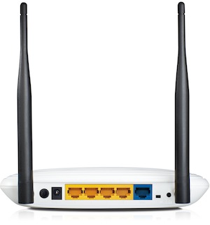
The TL-WR841N contains four LAN ports, all belonging to the same network. With vlans, it is possible to configure those LAN ports in different manner, so that the device does not behave anymore as a switch on the 4 ports. For example, it would be possible to setup the two leftmost ports on a virtual lan: devices connected into these ports would see each other, but would have no routing to devices plugged into the rightmost ports.
Full information on vlans in OpenWrt can be found in the network interfaces document. This page includes information specific to the TL-WR841N router, configured with OpenWrt (Attitude Adjustment 12.09 release).
The default /etc/config/network configuration looks like:
config interface 'loopback'
        option ifname 'lo'
        option proto 'static'
        option ipaddr '127.0.0.1'
        option netmask '255.0.0.0'

config interface 'lan'
        option ifname 'eth1'
        option type 'bridge'
        option proto 'static'
        option ipaddr '192.168.1.1'
        option netmask '255.255.255.0'

config interface 'wan'
        option ifname 'eth0'
        option proto 'dhcp'

config switch
        option name 'switch0'
        option reset '1'
        option enable_vlan '1'

config switch_vlan
        option device 'switch0'
        option vlan '1'
        option ports '0 1 2 3 4'
So there is a switch identified as switch0. To get info on this switch:
swconfig dev switch0 help
Which outputs:
switch0: eth1(AR934X built-in switch), ports: 5 (cpu @ 0), vlans: 16
     --switch
        Attribute 1 (int): enable_vlan (Enable VLAN mode)
        Attribute 2 (none): apply (Activate changes in the hardware)
        Attribute 3 (none): reset (Reset the switch)
     --vlan
        Attribute 1 (int): vid (VLAN ID)
        Attribute 2 (ports): ports (VLAN port mapping)
     --port
        Attribute 1 (int): pvid (Primary VLAN ID)
        Attribute 2 (string): link (Get port link information)
So this device supports 16 vlans, and the port 0 is the CPU port; ports 1,2,3,4 are associated to the 4 LAN connections on the back of the router.
To get the exact matching between ports and the labelling on the router, enter now:
swconfig dev switch0 show
And play with connecting cables to the LAN connections. For this router, I got the following allocation:
Port 0: CPU
Port 1: LAN 4
Port 2: LAN 1
Port 3: LAN 2
Port 4: LAN 3
With the existing configuration, there is a single virtual lan, with identity 0, identified as eth1.0 (or directly eth1).
To configure two virtual lans, one associated to the left ports (LAN 1, LAN 2 / ports 2 and 3), and other associated to the right ports (LAN 3, LAN 4 / ports 1 and 4), we use the following configuration:
config interface 'loopback'
        option ifname 'lo'
        option proto 'static'
        option ipaddr '127.0.0.1'
        option netmask '255.0.0.0'

config interface 'lan'
        option ifname 'eth1.1'
        option type 'bridge'
        option proto 'static'
        option ipaddr '192.168.1.1'
        option netmask '255.255.255.0'

config interface 'landenver'
        option ifname 'eth1.2'
        option type 'bridge'
        option proto 'static'
        option ipaddr '192.168.2.1'
        option netmask '255.255.255.0'

config interface 'wan'
        option ifname 'eth0'
        option proto 'dhcp'

config switch
        option name 'switch0'
        option reset '1'
        option enable_vlan '1'

config switch_vlan 'eth1_1'
        option device 'switch0'
        option vlan '1'
        option ports '2 3 0t'

config switch_vlan 'eth1_2'
        option device 'switch0'
        option vlan '2'
        option ports '1 4 0t'
This creates an interface called lan associated to the first vlan (eth1.1), that is, to the ports labelled in the router as LAN 1, LAN2; it also creates the interface landenver associated to the second vlan (eth1.2), on the remaining router ports. Note that each interface uses a different set of LAN ports (2,3 vs 1,4) and both obviously communicate with the CPU (port 0). As both access the port 0, this is tagged (0t). Detailed information on this logic is included in the switch documentation on the OpenWRT wiki page.
With this configuration, entering now (after restarting the network with /etc/init.d/network restart:
swconfig dev switch0 show
Will output:
Global attributes:
        enable_vlan: 1
Port 0:
        pvid: 0
        link: port:0 link:up speed:1000baseT full-duplex txflow rxflow
Port 1:
        pvid: 2
        link: port:1 link:up speed:100baseT full-duplex auto
Port 2:
        pvid: 1
        link: port:2 link:up speed:100baseT full-duplex auto
Port 3:
        pvid: 1
        link: port:3 link:down
Port 4:
        pvid: 2
        link: port:4 link:down
VLAN 0:
        vid: 0
        ports: 0t
VLAN 1:
        vid: 1
        ports: 0t 2 3
VLAN 2:
        vid: 2
        ports: 0t 1 4
For this to fully work, we need to provide additional firewall rules, and setup dhcp for the new interface (landenver): enter in /etc/config/firewall the following new lines:
config zone
      option name             landenver
      option network          'landenver'
      option input            ACCEPT
      option output           ACCEPT
      option forward          REJECT
and, in /etc/config/dhcp add now:
config dhcp landenver
      option interface        landenver
      option start            200
      option limit            250
      option leasetime        12h
Time now to restart the network, and enjoy the different virtual lans:
/etc/init.d/network restart